How to Use Measurement Designer
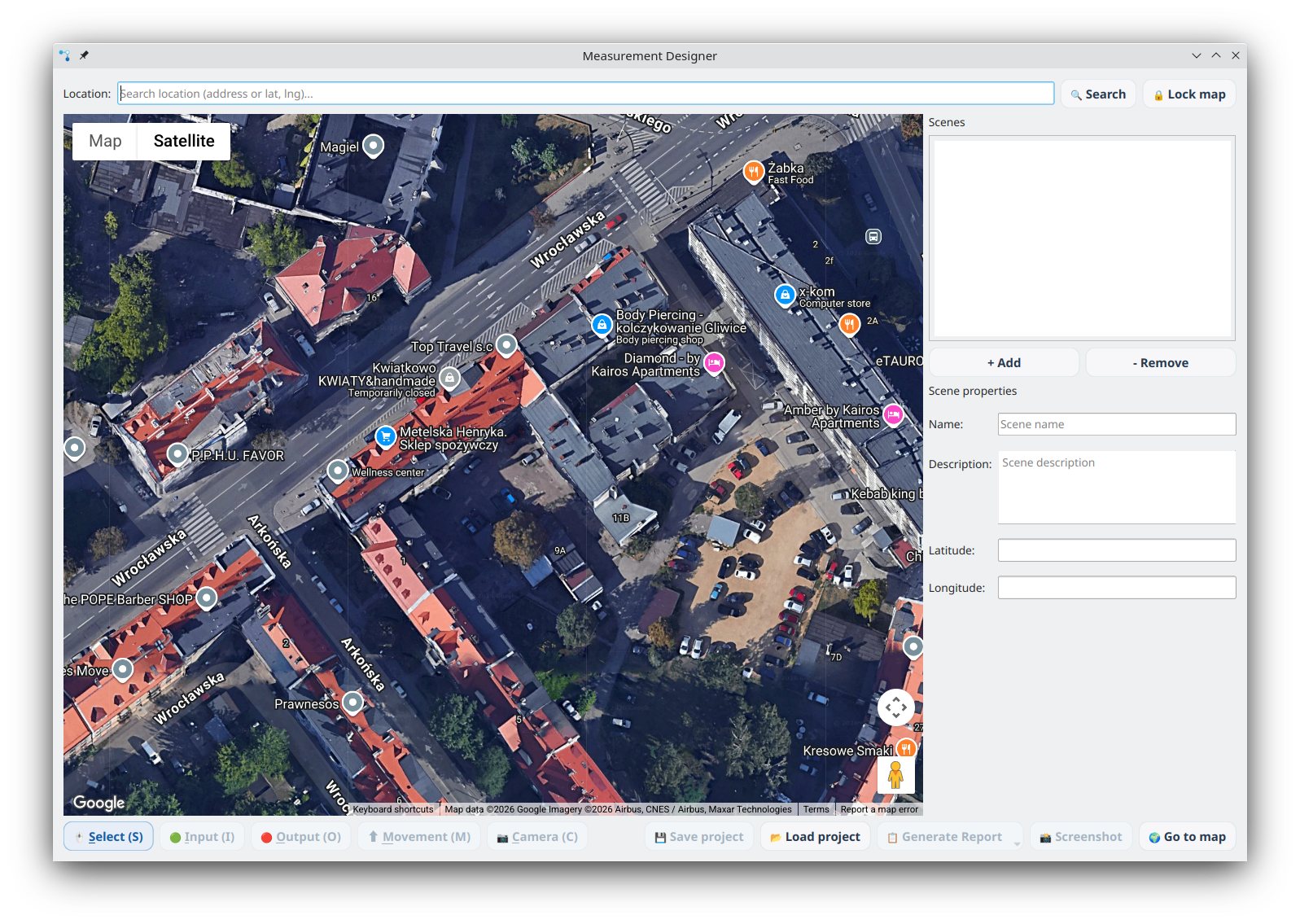
Measurement Designer is a built-in AITracker GUI tool for planning intersection measurements on a satellite map. It lets you plan camera placement, define traffic inputs and outputs, and draw traffic movements on the real map view.
Overview
Measurement Designer helps traffic engineers:
- Visually plan traffic measurement points on a satellite map
- Define inputs (entry points) and outputs (exit points) on intersections
- Draw traffic movements between inputs and outputs
- Place and orient cameras to cover measurement zones
- Assess camera coverage requirements at a glance
- Work with multiple geographic scenes in a single project
- Save and share intersection designs as .aispdesign files
Launching Measurement Designer
Open the tool from the main menu:
Menu → Tools → Measurement Designer (shortcut: Ctrl+M)
A dialog window will open with a map view and a toolbar.
Step 1: Find Your Location
When the dialog opens, you will see a satellite map (Google Maps).
- Type an address or coordinates (e.g.,
50.291, 18.671) in the search bar at the top - Click Search (or press Enter)
- The map will navigate to the specified location
- Use the map controls to zoom in/out and adjust the view until you have a clear satellite view of the intersection
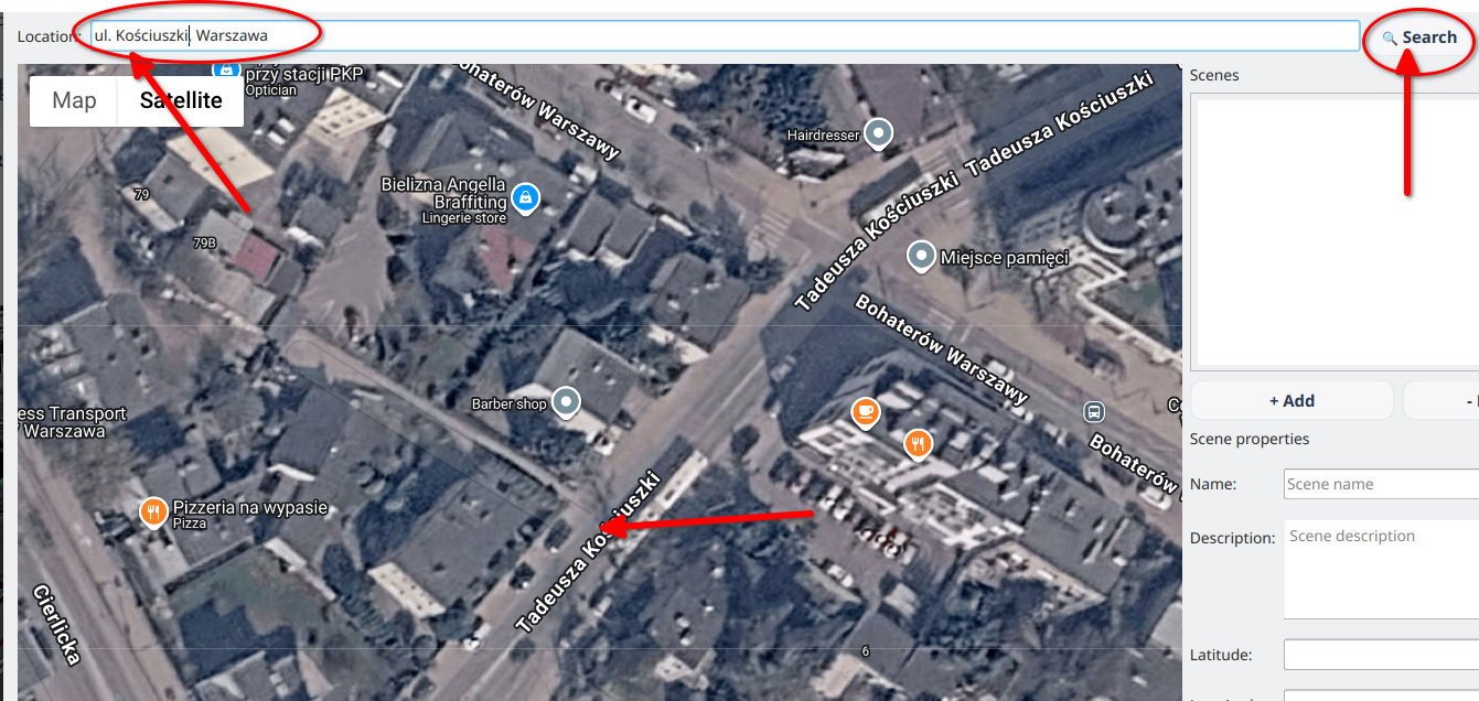
💡 Tip: Zoom level 18–20 works best for intersection design. Make sure the entire intersection is visible.
Step 2: Lock the Map
Once you have positioned the map correctly:
- Click the Lock map button
- The satellite view will be captured as a background image
- The view switches to Designer mode — you can now draw on the captured map
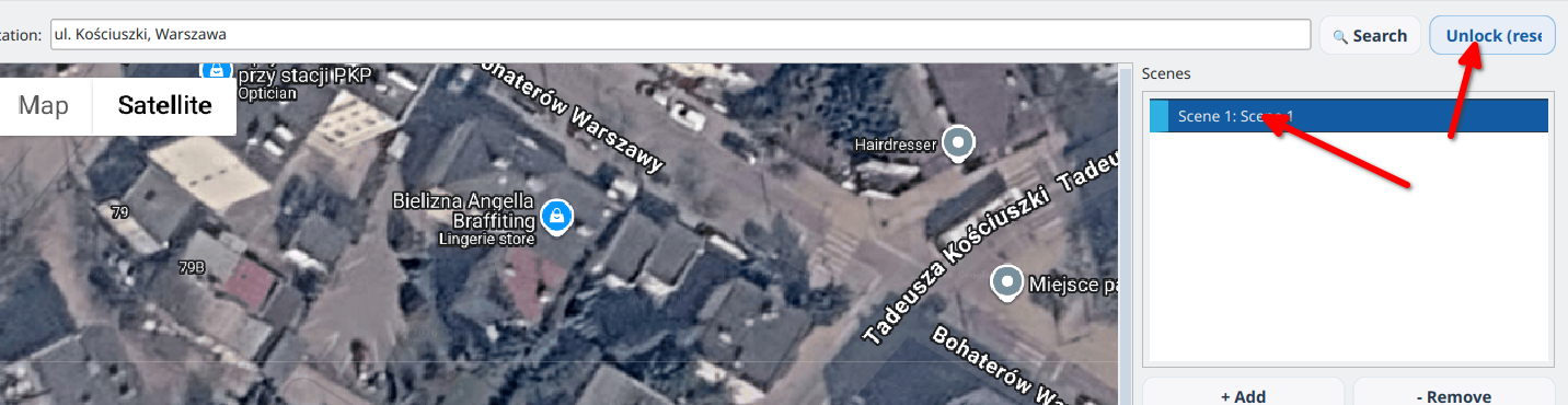
The lock button changes to Unlock (reset). Clicking it will return you to the map view (with a confirmation dialog, as this discards the current design).
⚠️ Important: Locking the map freezes the current view. Make sure the intersection is properly centered and zoomed before locking.
Step 3: Place Input Nodes (Green)
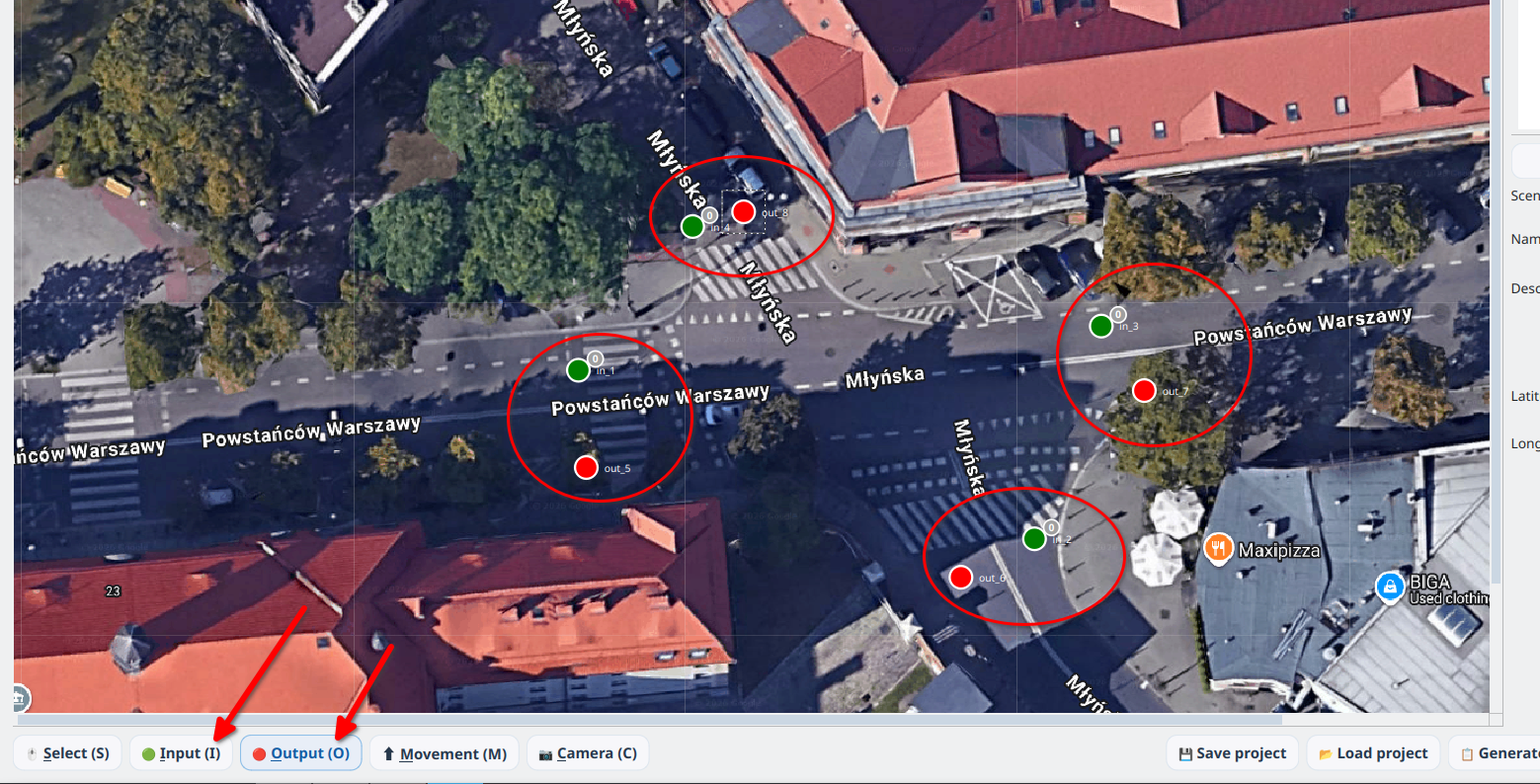
Input nodes represent traffic entry points — where vehicles enter the intersection.
- Select the Input tool from the toolbar
- Click on the map where you want to place an input node
- A green circle will appear at that position
- Repeat for all entry points
Each input node displays a coverage badge in the upper-right corner:
- Grey 0 — no movements connected (unmonitored)
- Green 1 — one movement is connected to the input
- Orange N! (for example, 3!) — several movements are connected to the input and their complete paths require camera coverage
The badge describes the number of movements, not the required number of cameras. Choose cameras according to visibility along the complete paths, occlusions, resolution, and scene geometry.
Step 4: Place Output Nodes (Red)
Output nodes represent traffic exit points — where vehicles leave the intersection.
- Select the Output tool from the toolbar
- Click on the map where you want to place an output node
- A red circle will appear at that position
- Repeat for all exit points
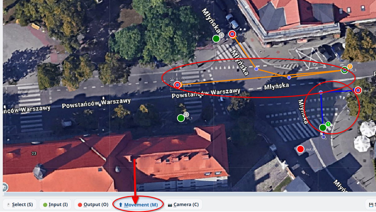
Step 5: Draw Traffic Movements
Movements represent traffic flows — the paths vehicles take from inputs to outputs.
- Select the Movement tool from the toolbar
- Click on an Input node (green) to start the movement
- Click on empty space to add intermediate waypoints (optional — the line follows the road shape)
- Click on an Output node (red) to finish the movement
- A blue line with an arrowhead will appear connecting the input to the output
Movement Colors
- Blue — default color, single movement from an input
- Orange — warning color applied when more than one movement originates from the same input; it prompts a coverage check but does not determine the number of cameras
Editing Movements
- Intermediate waypoints can be dragged to adjust the path shape
- Start and end points are locked to their respective nodes and move with them
- Press Delete to remove a selected movement
- Press Escape to cancel a movement being drawn
💡 Tip: Movements are drawn below nodes (lower layer), so they never obscure the input/output markers.
Step 6: Place Cameras (Yellow)
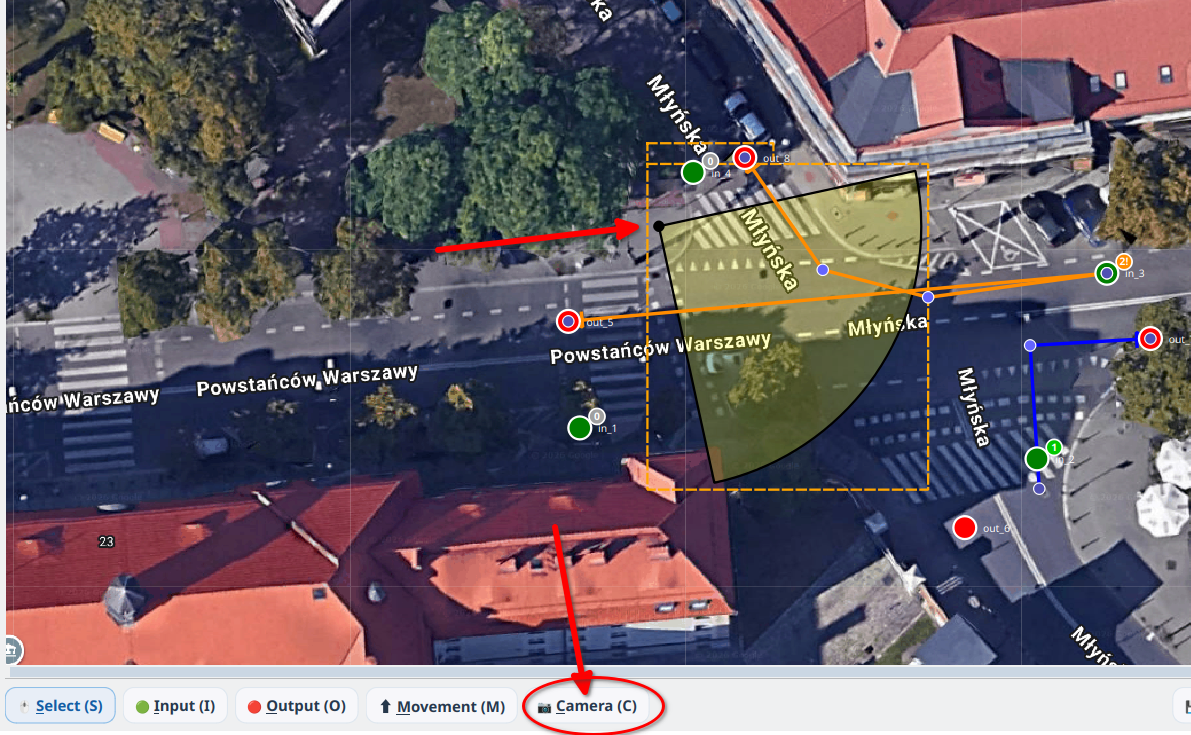
Camera items represent the planned camera positions and their field of view.
- Select the Camera tool from the toolbar
- Click on the map to place a camera
- A yellow arc/wedge will appear showing the camera's field of view
Camera Interactions
| Action | Mouse Gesture | Description |
|---|---|---|
| Move camera | LMB drag on center point | Repositions the entire camera |
| Rotate camera | RMB drag | Rotates the camera direction (0–360°) |
| Adjust FOV | Shift + LMB drag | Makes the viewing angle wider or narrower |
| Adjust range | LMB drag on arc area | Increases or decreases the camera's reach |
Camera Planning Tips
- Position cameras so their field of view covers the relevant input nodes
- For every input, verify that the camera fields of view cover the complete paths of all movements, not only the input node.
- A green or orange badge does not specify the camera count. One camera can cover several movements when their complete paths remain visible; even one movement can require multiple cameras when it is occluded or lacks sufficient image resolution.
Step 7: Working with Multiple Scenes
A single project can contain multiple geographic scenes — for example, different intersections in the same area.
Scene Sidebar
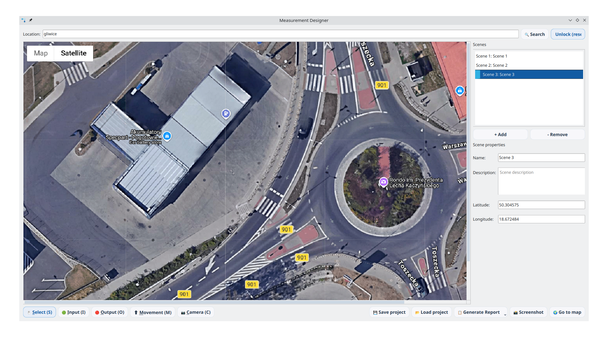
On the right side of the dialog, you will see the Scenes panel: - A list of all scenes in the current project - + Add button to create a new scene - - Remove button to delete the selected scene
Adding a New Scene
- Click + Add in the sidebar
- The view switches back to the map
- Search for the new location
- Lock the map — a new scene is created automatically
- Design the new intersection
Switching Between Scenes
Click on a scene name in the sidebar list to switch to it. The designer view will update to show that scene's map background and all its elements.
⚠️ Note: Your work on the current scene is automatically saved when you switch to another scene.
Step 8: Saving Your Project
- Click Save project in the toolbar (or press
Ctrl+S) - On the first save, choose a location and filename in the file dialog
- The project is saved as an
.aispdesignfile - Subsequent saves (
Ctrl+Sor button) automatically overwrite the same file — no dialog is shown
💡 Quick save: Once a project has been saved or loaded from a file, pressing
Ctrl+Ssaves instantly without prompting.
File Format
The .aispdesign file is a ZIP archive containing:
- project.json — project metadata (number of scenes, active scene index)
- scene1.json, scene2.json, … — data for each scene (nodes, movements, cameras, coordinates)
- map1.png, map2.png, … — satellite map background for each scene
Step 9: Loading a Project
- Click Load project in the toolbar
- Select an
.aispdesignfile (or a legacy.jsonfile from older versions) - The project will be loaded with all scenes, map backgrounds, and design elements
💡 Backward compatibility: Older single-scene
.jsonprojects are automatically converted to the new multi-scene format when loaded.
Step 10: Taking a Screenshot
Click Screenshot in the toolbar to save an image of the current design view.
- On Linux: saved to
~/Obrazy/ - On Windows: saved to
~/Pictures/ - Filename format:
AISP_Designer_YYYYMMDD_HHMMSS.png
Keyboard Shortcuts
| Key | Action |
|---|---|
Ctrl+M |
Open Measurement Designer (from main window) |
Ctrl+S |
Save project (quick save if path is known) |
Enter |
Confirm search location |
Delete |
Remove selected item(s) |
Escape |
Cancel current movement drawing |
Visual Reference
Element Colors
| Element | Color | Description |
|---|---|---|
| Input node | 🟢 Green | Traffic entry point |
| Output node | 🔴 Red | Traffic exit point |
| Movement (single) | 🔵 Blue | Normal movement |
| Movement (warning) | 🟠 Orange | Multiple movements from same input |
| Camera FOV | 🟡 Yellow (semi-transparent) | Camera field of view wedge |
| Coverage badge | Grey / Green / Orange | Input coverage indicator |
Coverage Badge Guide
| Badge | Meaning | Action Required |
|---|---|---|
Grey 0 |
No movements connected | Connect at least one movement |
Green 1 |
Single movement | Verify visibility along the complete movement path |
Orange N! |
Multiple movements (N) | Verify complete coverage of every path and choose the camera count from actual visibility |
Best Practices
- Start with inputs and outputs — place all nodes before drawing movements
- Use waypoints for curved roads — click along the road to make movements follow the actual path
- Check coverage badges — ensure every input has at least one movement (no grey badges)
- Plan cameras after movements — badges identify inputs with multiple movements, but choose the camera count only after checking visibility along every complete path
- Use multiple scenes for large projects covering several intersections
- Save frequently — use
Save projectafter significant changes - Name your scenes descriptively — helps when working with many intersections
Troubleshooting
Map doesn't load
- Ensure you have an active internet connection
- Check if QtWebEngine is installed (required for the map view)
Cannot draw movements
- Make sure the map is locked (designer mode active)
- Movements must start on an Input (green) node
- Movements must end on an Output (red) node
Elements not visible after loading
- Verify the
.aispdesignfile is not corrupted - Check if the correct scene is selected in the sidebar
Camera arc not responding to mouse
- Rotate: use Right Mouse Button drag
- FOV: use Shift + Left Mouse Button drag
- Range: use Left Mouse Button drag on the arc (not the center point)
Measurement Designer is part of AITracker GUI's intersection planning toolkit, helping traffic engineers design optimal camera placement and measurement configurations.