Distance Object — Speed Measurement
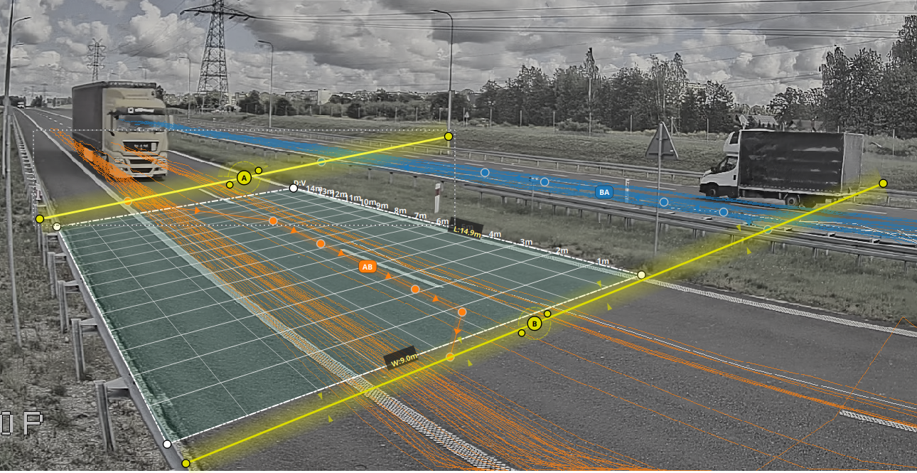
The distance object measures the speed of vehicles moving through the video. It is a scene-configuration element defined by a quadrilateral whose dimensions are specified in metres.
How speed measurement works
- Define the polygon — mark four points in the video that represent a known area of the road.
- Enter real-world dimensions — specify the width and length of that area in metres.
- Track trajectories — as vehicles pass through the polygon, their trajectories are tracked frame by frame.
- Calculate speed — distance travelled in metres divided by time in seconds gives the vehicle speed.
Configuration
Distance-zone parameters
To allow AITracker to estimate speed, define a Distance object in the scene configuration with the following values:
| Parameter | Type | Description |
|---|---|---|
trajectory |
4 points | Four corner points of the measurement zone, using relative coordinates from 0.0 to 1.0 |
width |
float | Actual zone width in metres |
length |
float | Actual zone length in metres |
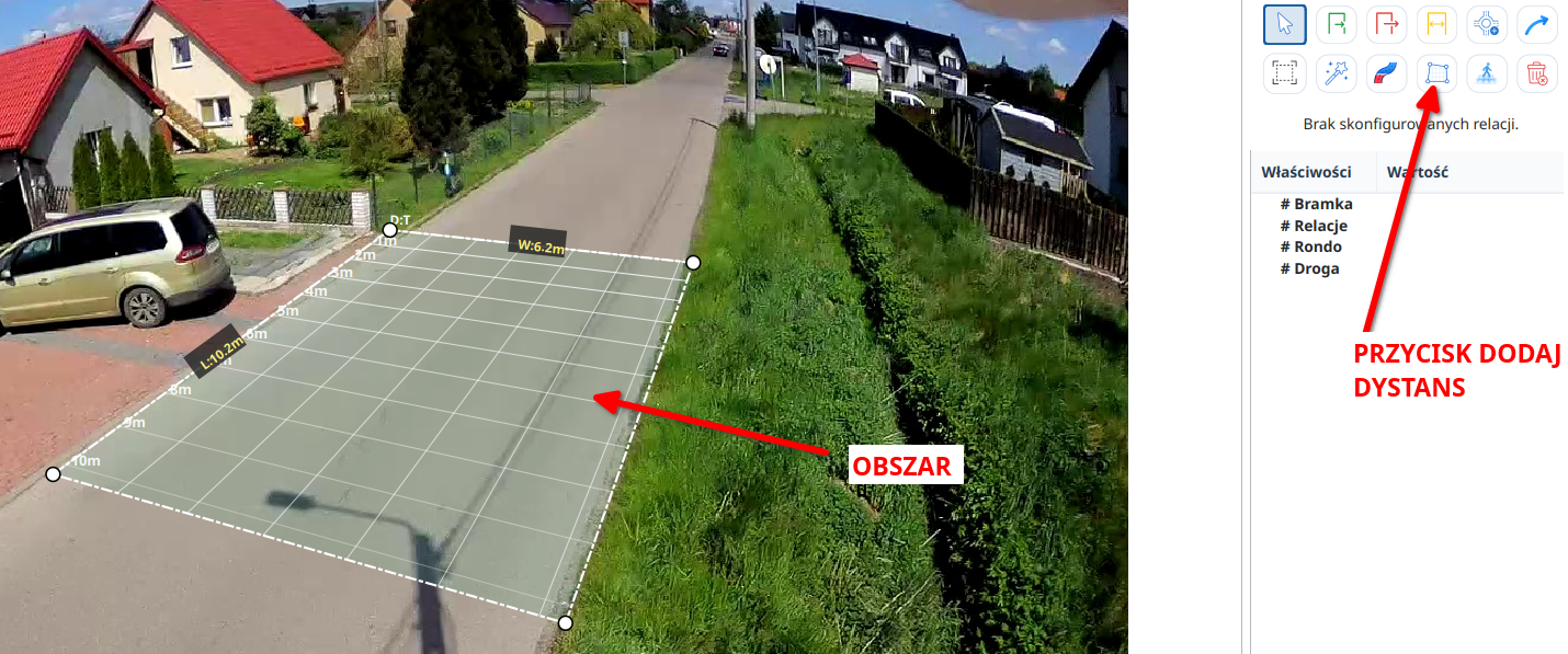
Defining the quadrilateral
The polygon must consist of four corner points representing a quadrilateral on the road surface:
Point 1 ─────────── Point 2
   │                   │
   │    MEASUREMENT    │
   │       ZONE        │
   │                   │
Point 4 ─────────── Point 3
Guidelines for placing the polygon:
- Place it on a flat section of road, without hills, bends, or elevation changes.
- Make sure it covers the full width of the lane used by the measured vehicles.
- A longer measurement zone generally gives a more accurate speed estimate.
- Avoid areas where vehicles frequently obscure one another.
- For the best accuracy, keep the camera view as perpendicular to the road as possible.
Real-world dimensions
Accurate speed measurement depends on precise real-world dimensions:
- Width — the transverse dimension of the polygon, across the road, in metres.
- Length — the longitudinal dimension, along the direction of the road, in metres.
Tip: Measure the road surface before configuring the video analysis. Road markings, lane widths, or objects of known size can also provide calibration references.
Tip: If exact measurements are unavailable, use a mapping service with a satellite-view distance measurement tool.
Technical parameters
Speed measurement uses several thresholds:
| Parameter | Default | Description |
|---|---|---|
max_velocity |
160 km/h | Higher values are rejected as invalid |
min_time_in_the_zone_ms |
500 ms | Minimum time a vehicle must remain in the zone for a valid measurement |
remove_frames_percent |
10% | Boundary frames removed to reduce noise |
Categories excluded from reports
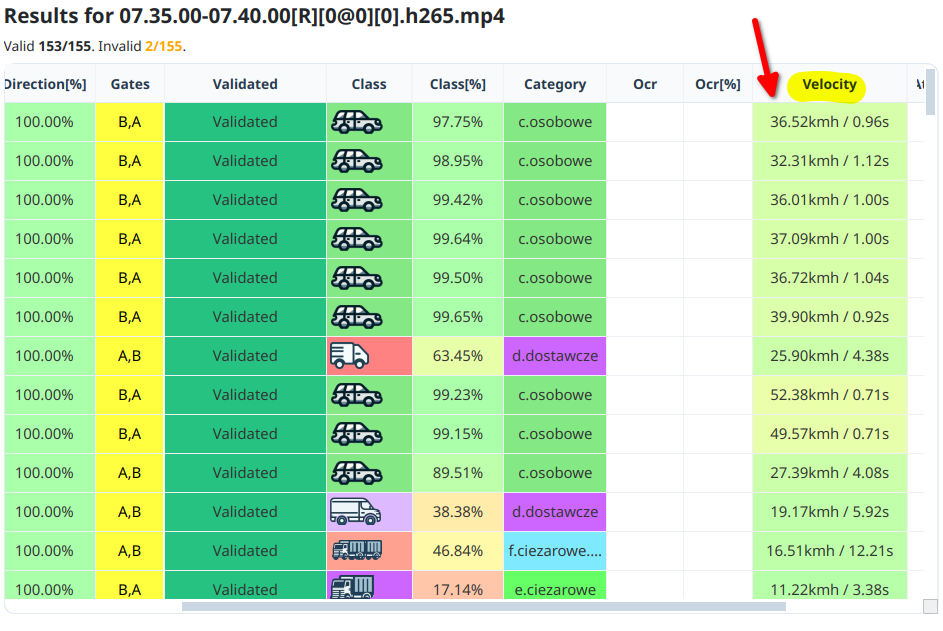
The application measures the speed of every object and displays it in the vehicle table. The following categories are excluded from generated speed reports:
- bicycles and electric bicycles,
- personal transporters,
- scooters,
- all pedestrian categories,
- trains,
- emergency vehicles.
Measurement accuracy
| Aspect | Value |
|---|---|
| Typical accuracy | ±5–10% |
| Best conditions | Flat road, perpendicular camera view, and unobstructed visibility |
Important: This speed value is an estimate and is not certified for law enforcement or traffic-offence processing. It is suitable for traffic studies, planning, and general analysis.
Generated output
Velocity.csv
The main output file contains:
| Column | Description |
|---|---|
Time |
Timestamp at which the vehicle was measured |
Direction |
Travel direction based on movement classification |
Label |
Vehicle category |
Velocity |
Measured speed in km/h |
Distance |
Distance travelled in metres |
Timespan |
Time spent in the measurement zone, in seconds |
Velocity.xlsx
The workbook contains one worksheet per movement containing a valid speed measurement. Every worksheet uses the same complete time axis from the earliest to the latest population record, aligned to the grouping period selected for the report. Missing intervals are filled with zeros. Speed columns use right-closed ranges with widths of 10 km/h or 5 mph. The displayed range reaches at least the configured upper boundary and expands to include the greatest measured speed. The defaults are 140 km/h and 90 mph; they can be changed through reporter.decorator.velocity.minimum_velocity_range_kmh and reporter.decorator.velocity.minimum_velocity_range_mph. Every worksheet ends with totals, speed-range shares, and V50, V85, and V95.
Visualizations
AITracker generates:
VelocityScatter.png— an optional diagnostic scatter plot of all measured speeds over time; it is generated only whenreporter.decorator.velocity.include_diagnostic_scatteris enabled.Velocity.png— average speed for each hour,VelocityPerCategory.png— average speed for each vehicle category,VelocityDistribution.png— a histogram of the speed distribution.
Report
The generated Report.docx contains:
- speed statistics by direction,
- speed statistics by vehicle category,
- measurement-precision analysis,
- a summary of speed-limit violations when limits are configured.
Best practices
- Camera placement
- Mount the camera high enough to show the entire measurement zone.
- Avoid extreme angles that distort perspective.
- Make sure the camera is stable and does not shake or move.
- Zone design
- Use a zone at least 10 m long for reliable measurements.
- Match the zone width to the actual lane width.
- Place the zone away from intersections and stopping areas.
- Calibration
- Use objects of known size to verify the dimensions.
- If possible, test with vehicles travelling at a known speed.
- Take camera-lens distortion into account.
Speed measurement calibration checklist
- Calibrate the four-point polygon on a straight, accurately measured road section.
- Place the calibration area near the centre of the frame to reduce optical distortion.
- A section of approximately 10 m is practical; a longer section usually improves estimation stability.
- At 30 fps, estimates for fast vehicles are generally more stable than at 15 fps.
- Treat the result as an analytical estimate, not an enforcement measurement.
Limitations
- Accuracy depends on correct polygon dimensions.
- Very fast vehicles, above 160 km/h by default, may be filtered out.
- Curved roads reduce measurement accuracy.
- Camera shake affects trajectory precision.
- The measurement is not suitable for speed-law enforcement.