Gates — Counting Entries and Exits
Gates are control lines crossed by road users. In AITracker, they define entries and exits within the measurement area.
When to use gates
For a road cross-section measurement, bidirectional gates are usually the best choice. Two bidirectional gates and two movements, AB and BA, between them are sufficient.
At intersections and roundabouts, directional entry and exit gates are recommended. They count vehicles only when crossed in the configured direction, separating incoming and outgoing traffic.
If tracker trajectories at an intersection are very close together, replacing directional gates with bidirectional gates may prevent movement-classification errors.
When a bidirectional gate gives more stable results
- With complex roundabout geometry and tight curves, a bidirectional gate often gives more stable assignments than an entry/exit pair placed very close together.
- If the movement map shows many unclassified trajectories near the boundary between two directional gates, first try replacing them with a bidirectional gate.
Attaching gates to a roundabout
On a roundabout, both the drawn gate line and the angular position of its attachment point on the roundabout matter. Evaluate the position according to the direction of traffic around the roundabout.
- Attach an entry gate as early as possible, just after the beginning of the area where traffic from that approach joins the roundabout. This includes trajectories closer to the outer edge.
- Attach an exit gate as late as possible, near the end of the area where traffic leaves through that exit. This includes vehicles following different paths through the roundabout.
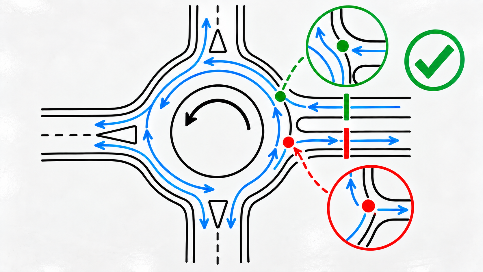
Apply this rule separately to every entry and exit. Attaching an entry gate too late or an exit gate too early can leave valid trajectories outside the movement.
How a gate works
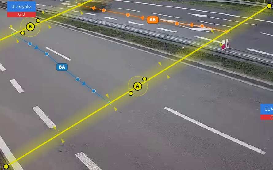
Each gate is defined by:
- ID — an automatically assigned letter such as A, B, C, or D,
- type — Entry, Exit, Bidirectional, or Pedestrian Crossing,
- curve position — the gate curve drawn by the user on the video frame,
- direction vector — an arrow perpendicular to the gate line; only crossings in the arrow direction are counted,
- gate crossing angle — the accepted crossing angle,
±75°by default, with a range of 0–90°.
Gate types
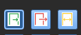
| Type | Colour | Symbol | Purpose |
|---|---|---|---|
| Entry | 🟢 Green | → | Entry point into the area |
| Exit | 🔴 Red | ← | Exit point from the area |
| Bidirectional | 🟡 Yellow | ↔ | Works as both an entry and an exit |
| Pedestrian Crossing | 🔵 Blue | 🚶 | Counts pedestrians and cyclists |
Creating gates
Step 1: Create the gates
- Go to Design → Gates.
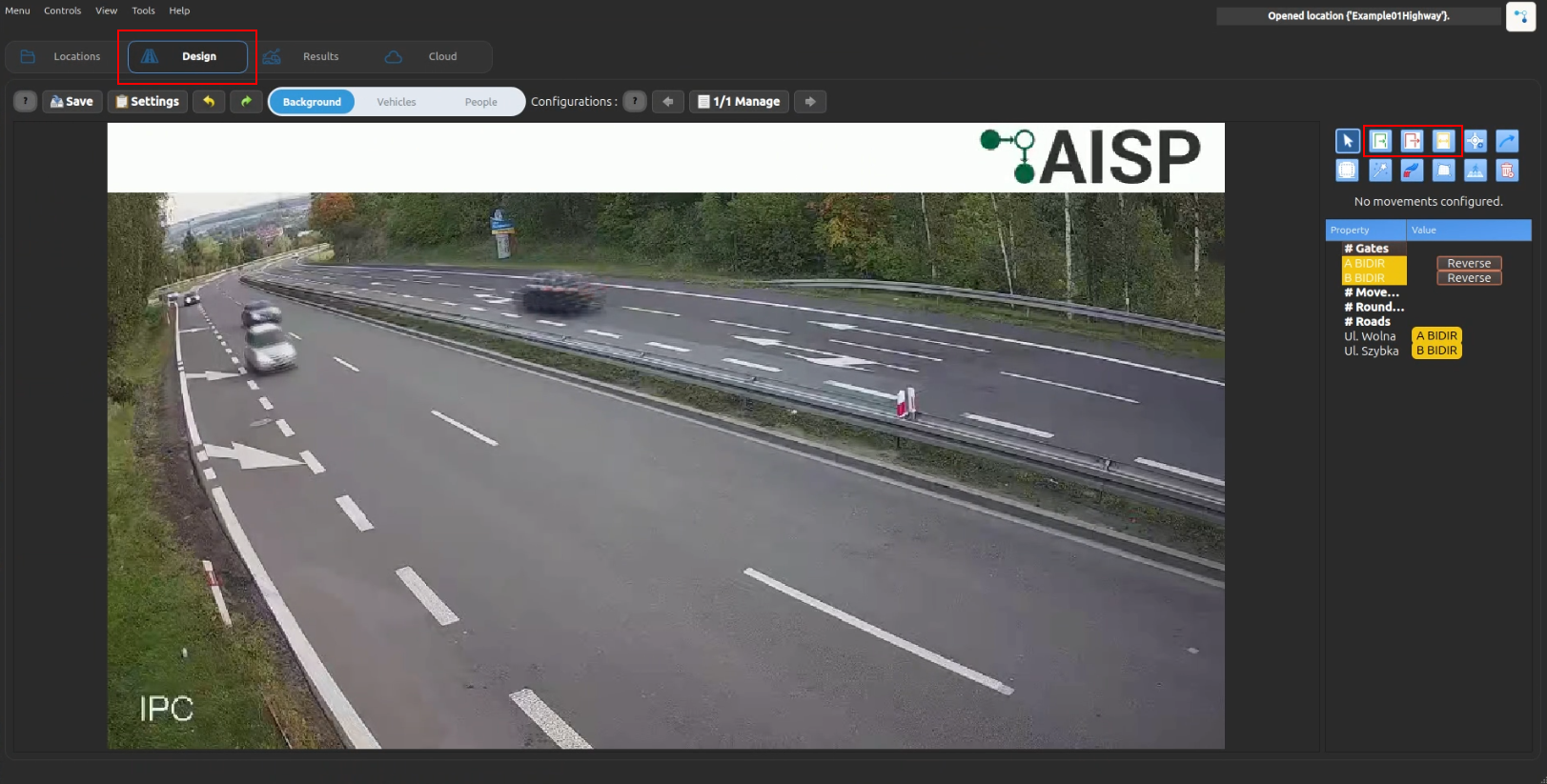
- Select the gate type: Entry, Exit, or Bidirectional.
- Click Add Gate.
- Draw a line on the video frame at the control point.
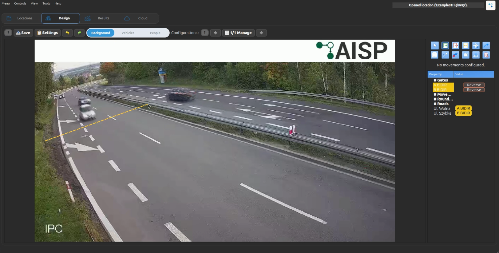
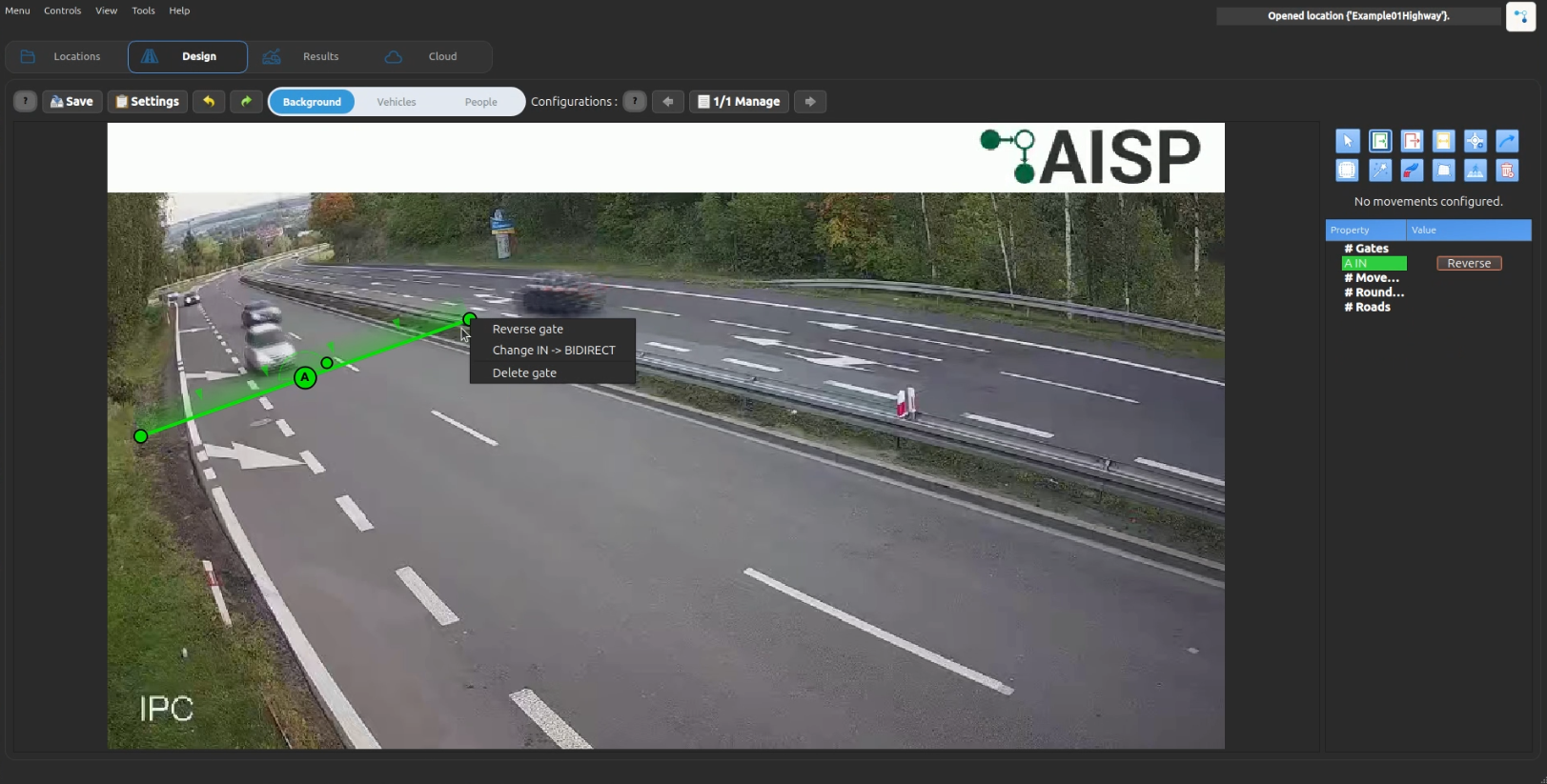
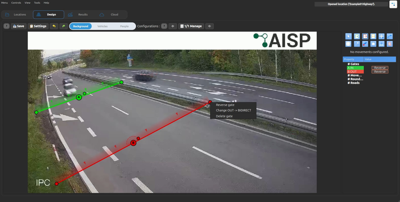
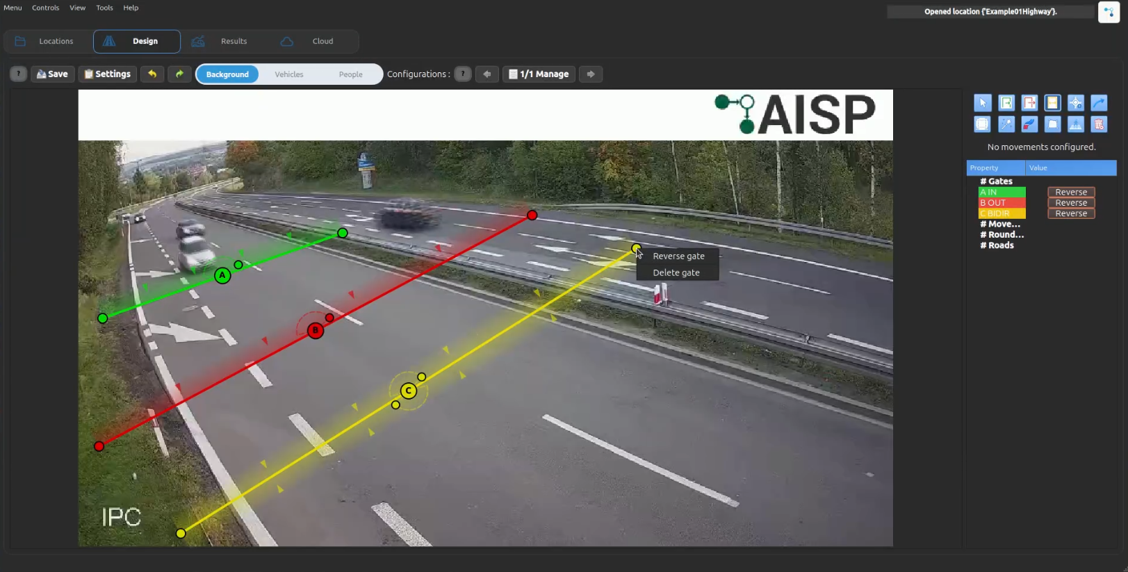
- Repeat this for all entry and exit points. At least two gates are required.
Gate crossing angle
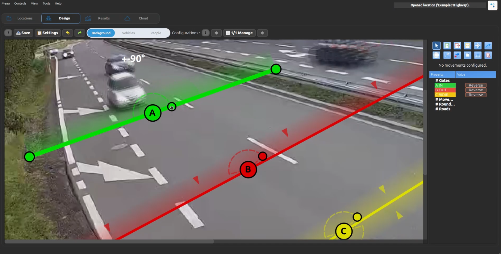
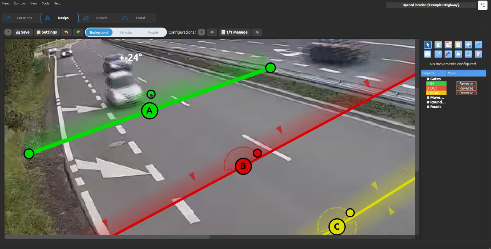
Drag the circular handle along the arc to change the accepted crossing angle. The handle remains anchored to the arc while dragging.
Troubleshooting incorrect movements caused by gates
Common causes
- The destination gate does not cross the full trajectory because it is too distant, too short, or incorrectly positioned.
- One or more gate directions are reversed.
- The final gate is not perpendicular to the dominant direction of travel.
- The movement configuration was corrected, but reclassification was not run after saving it.
Step-by-step correction
- Open Design → Gates and inspect the direction arrows on every gate.
- Use Reverse Gate Direction for any incorrectly oriented gate.
- Move the destination gate closer to the real paths and extend it so it crosses every trajectory assigned to that movement.
- Place the gate as perpendicular to the path of travel as possible.
- Correct the movements only after correcting the gates.
- Save the configuration and run reclassification.
- Check several boundary cases by object ID.
Recommended order of work
- Configure gate position, direction, length, and angle first; configure movements afterwards.
- Changing movements alone usually does not solve a problem caused by incorrect gate geometry.
Gate position, angle, and direction
- Place gates near the centre of the area where actual crossings occur, not on distant road sections.
- Correct gate direction and its angle relative to the dominant trajectory before refining movements.
- Sparse trajectories may not show a crossing as intuitively as a complete path; verify boundary cases using specific object IDs.
- If trajectories are very close or overlap, especially on roundabouts, use a bidirectional gate instead of an entry/exit pair.
Category filters
Open a gate card menu in the scene tree and select Add category filter. Accepted categories appear in the green area at the top of the editor; the gray palette below contains the remaining choices. The green funnel badge on the card shows how many categories are accepted.
- A gate without a filter accepts every category.
- An empty filter accepts no categories.
- Select Remove filters to restore unrestricted classification.