Gates and Movements Classification
Gates and Movements is a traffic analysis method in AITracker that allows for precise control over vehicle counting at intersections, parking lots, and complex traffic scenarios.
When to use Gates and Movements?
Use this classification method when:
- Intersections with multiple traffic directions
- Specific route analysis (left turn, right turn, straight ahead)
- Movements counting between specific control points
- Parking lots with entrances and exits
- Complex traffic patterns requiring explicit checkpoint definition
How it works
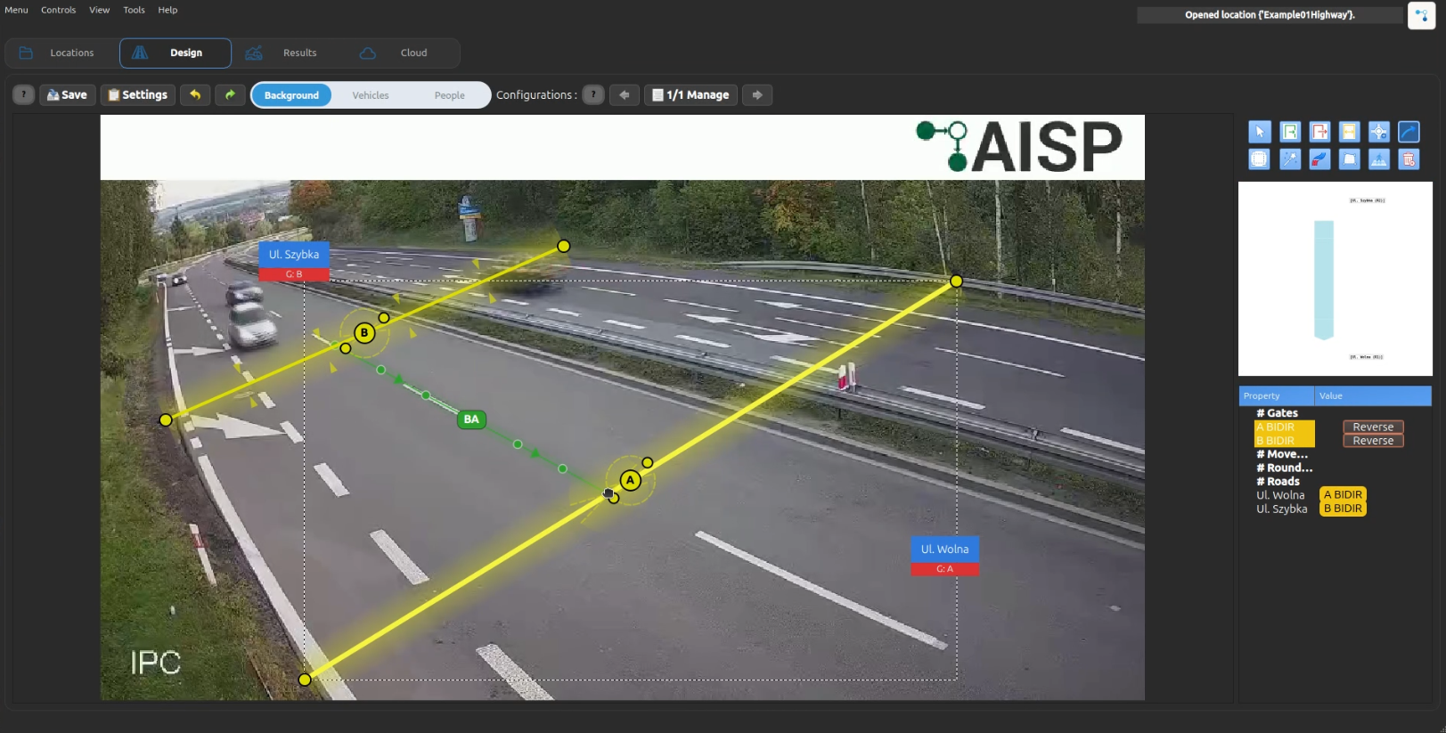
Gates
Gates are control points that vehicles pass through. Each gate is defined by:
- ID: Automatically assigned (A, B, C, D, ...)
- Type: Determines the gate's role
- Line position: Drawn on the video frame
- Direction vector: Arrow perpendicular to the gate line; only crossings in arrow direction are counted
- Crossing angle: Accepted direction cone around the gate direction vector, default
150°
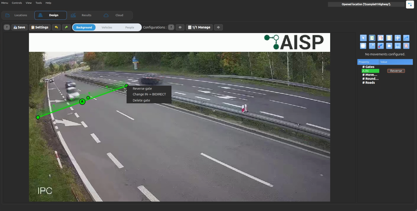
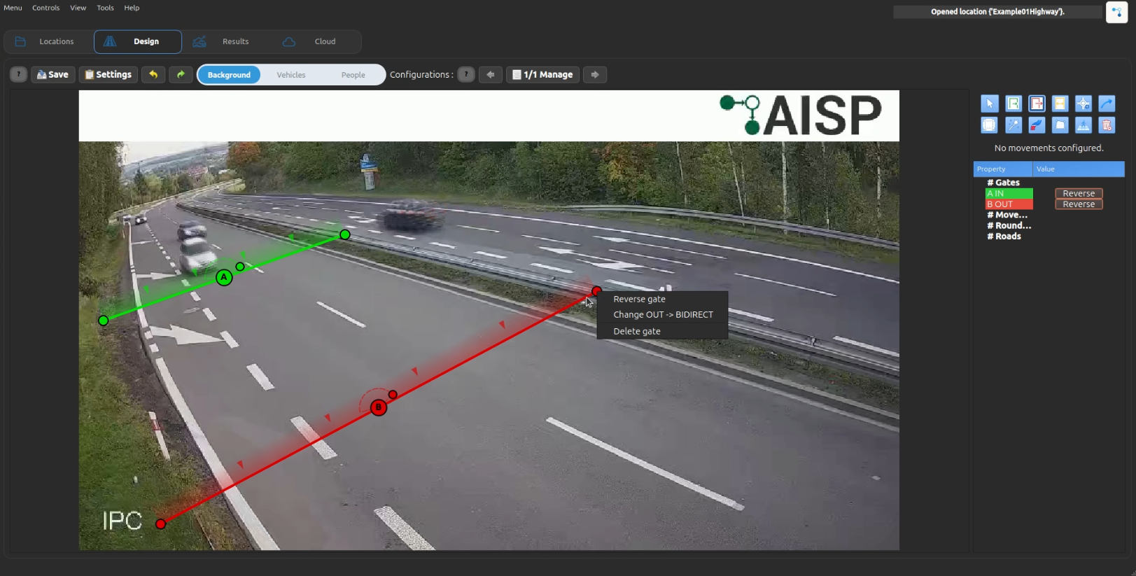
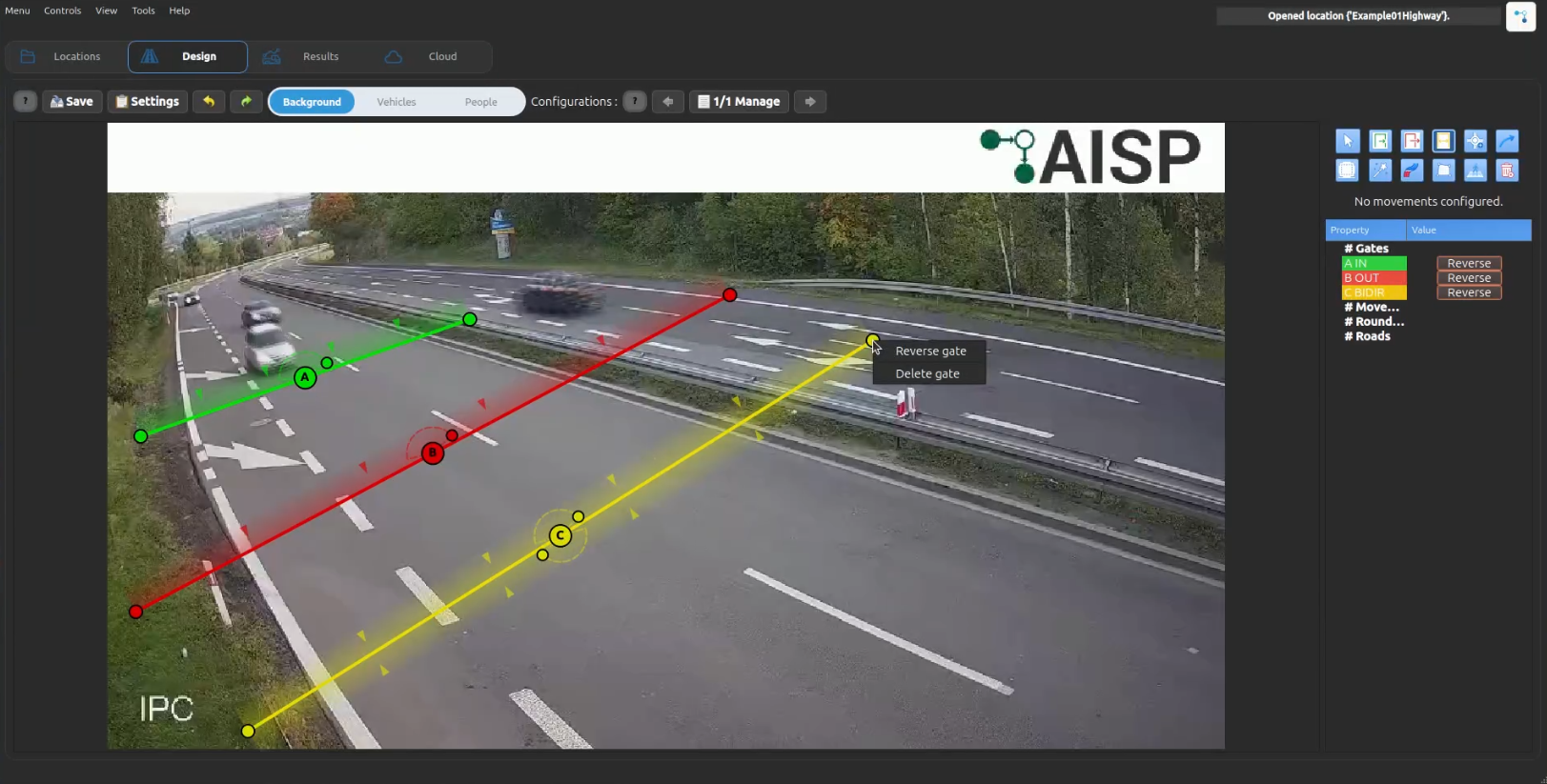
Gate Types
| Type | Color | Symbol | Purpose |
|---|---|---|---|
| Entry | 🟢 Green | → | Entry points to the area |
| Exit | 🔴 Red | ← | Exit points from the area |
| Bidirectional | 🟡 Yellow | ↔ | Serves as both entry and exit |
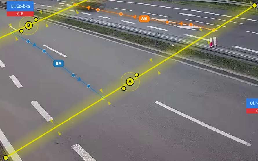
Movements (Routes)
Movements connect two gates to create possible travel routes. A movement cannot exist without gates:
- Movement ID: Automatically generated from gate pairs (e.g., AB, AC, BA)
- Direction: Derived from gate types
- Entry Gate → Exit Gate: Directional movement (shown with arrows)
- Color: Automatically assigned from color palette
- Dependency on gates: Each movement stores
EntryGateandExitGate; if a referenced gate is removed or its type changes, related movements must be recreated - Gate anchor points: Movement start/end are anchored at the exact clicked position on each gate line (not forced to gate midpoint)
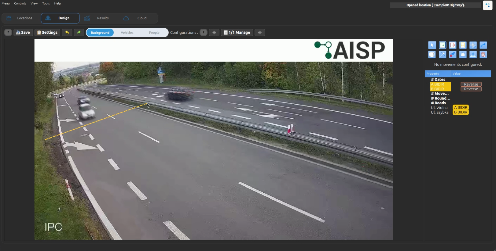
Creating Gates and Movements
Step 1: Create Gates
- Navigate to Design → Gates tab
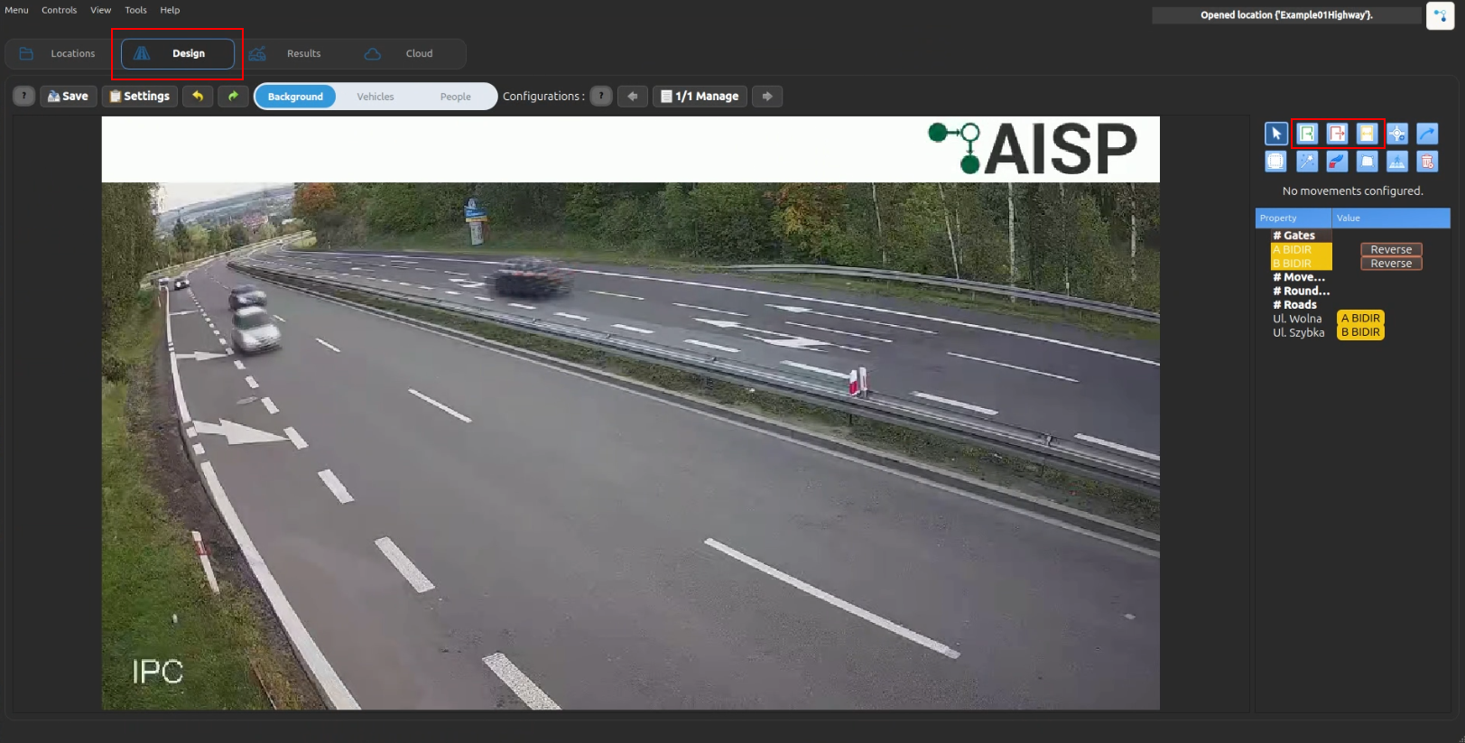
- Select gate type (Entry/Exit/Bidirectional)
- Click "Add Gate" button
- Draw a line on the video frame at the checkpoint location
- Repeat for all entry/exit points (minimum 2 gates)
Gate crossing angle

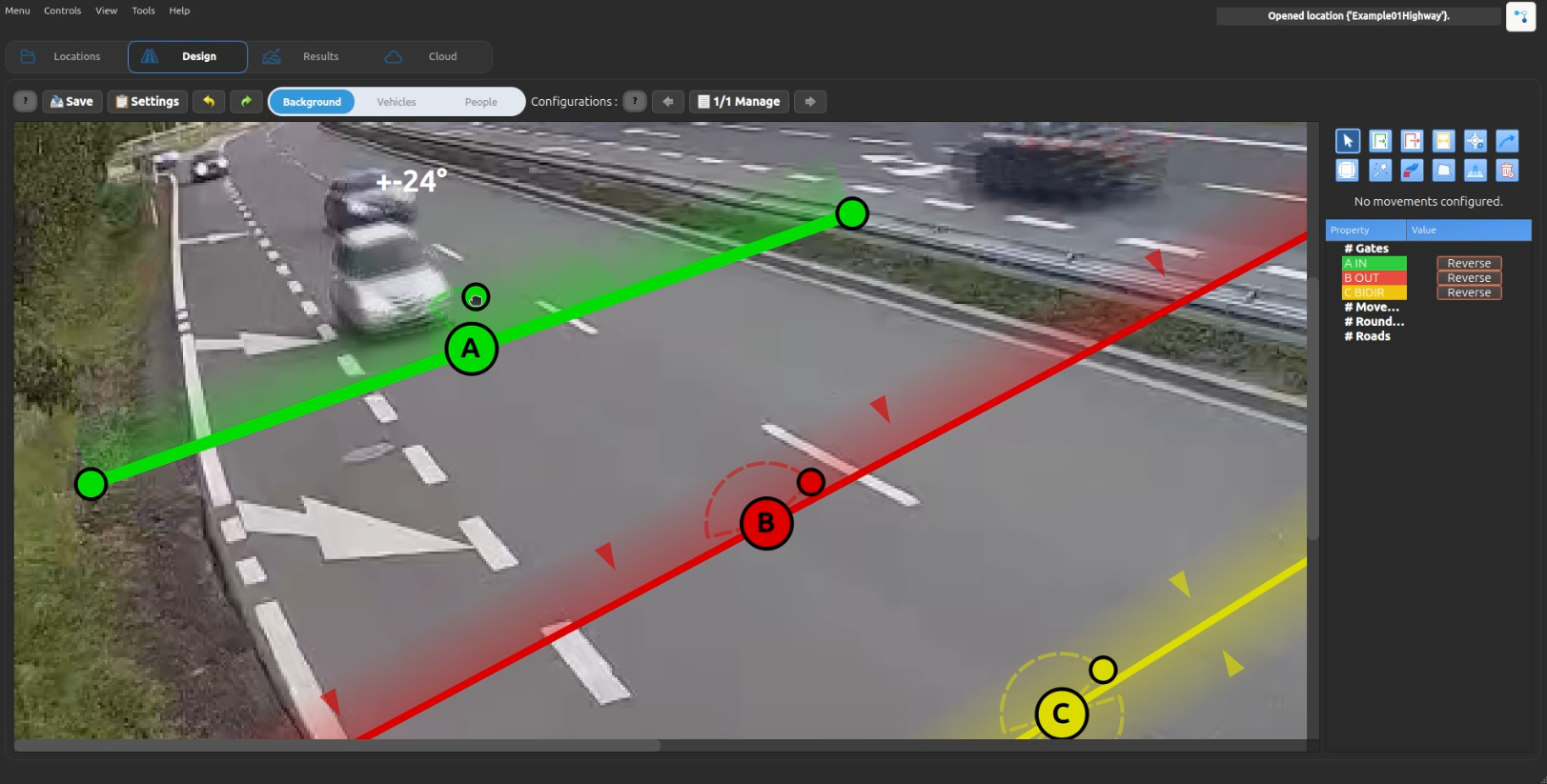
Each gate shows a semi-circle at its center. This marker visualizes the accepted crossing angle:
- The default angle is
75°. - Drag the handle on the semi-circle to change the angle.
- The current angle is displayed above the semi-circle while you drag the handle and disappears when you release it.
- Smaller values make crossing detection stricter; larger values allow more diagonal crossings.
- Entry and Exit gates show one semi-circle in the gate direction.
- Bidirectional gates show two mirrored semi-circles, one for each accepted direction.
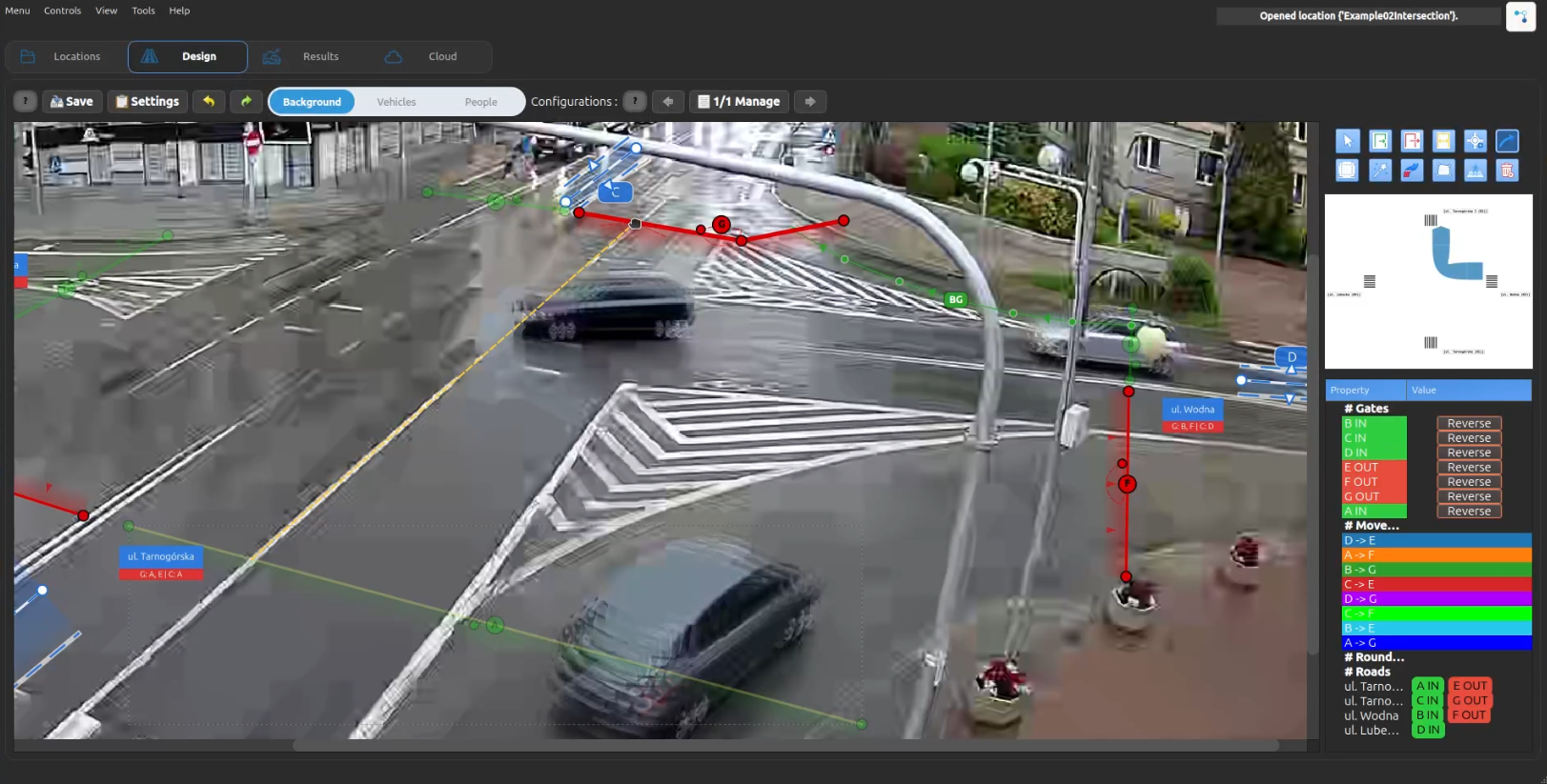
Step 2: Create Movements
- Navigate to Design → Movements tab
- Click "Add Movement" button
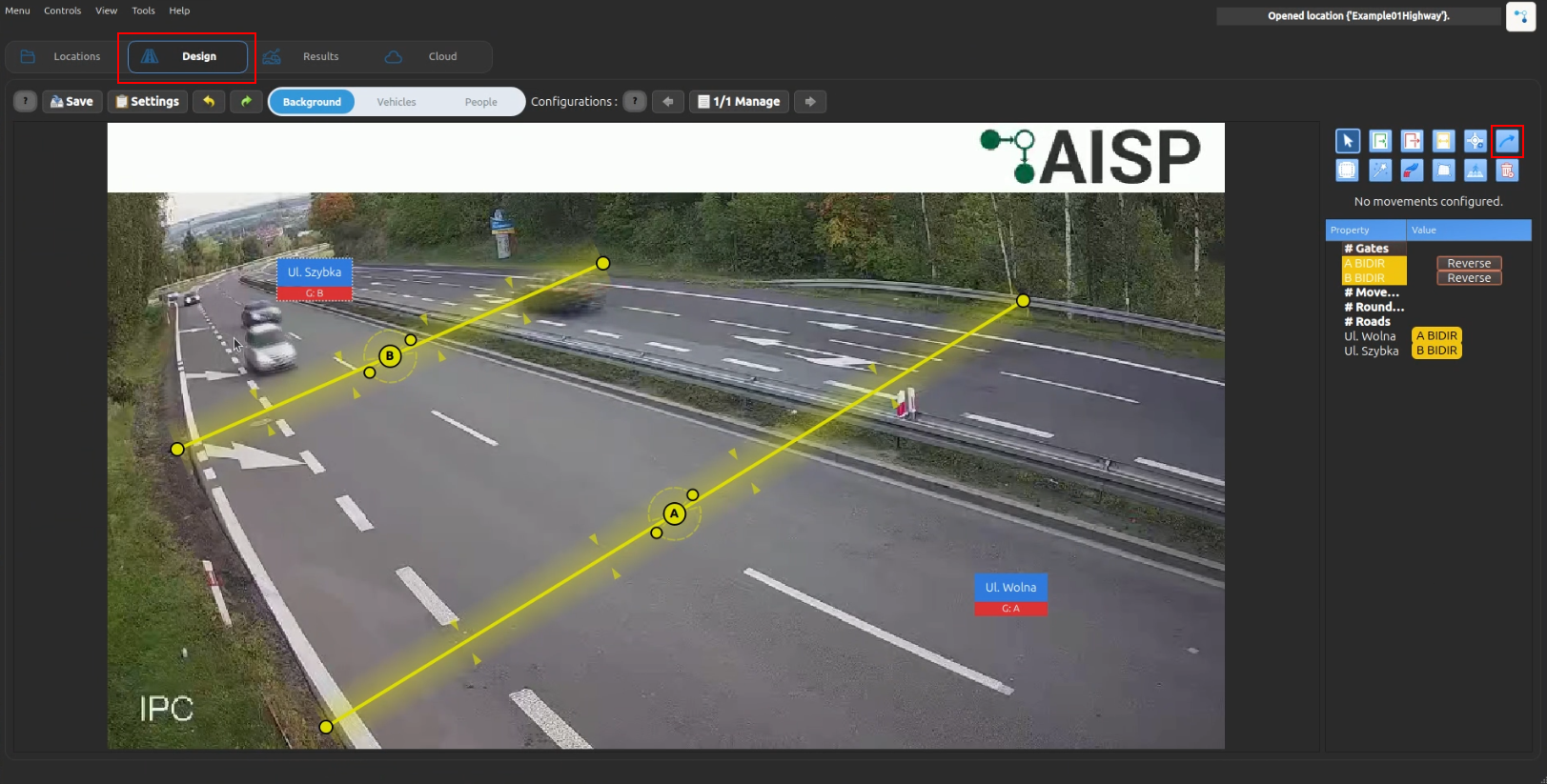
- Select source gate on image (entry point)
- Click the exact position on the source gate line where movement should start
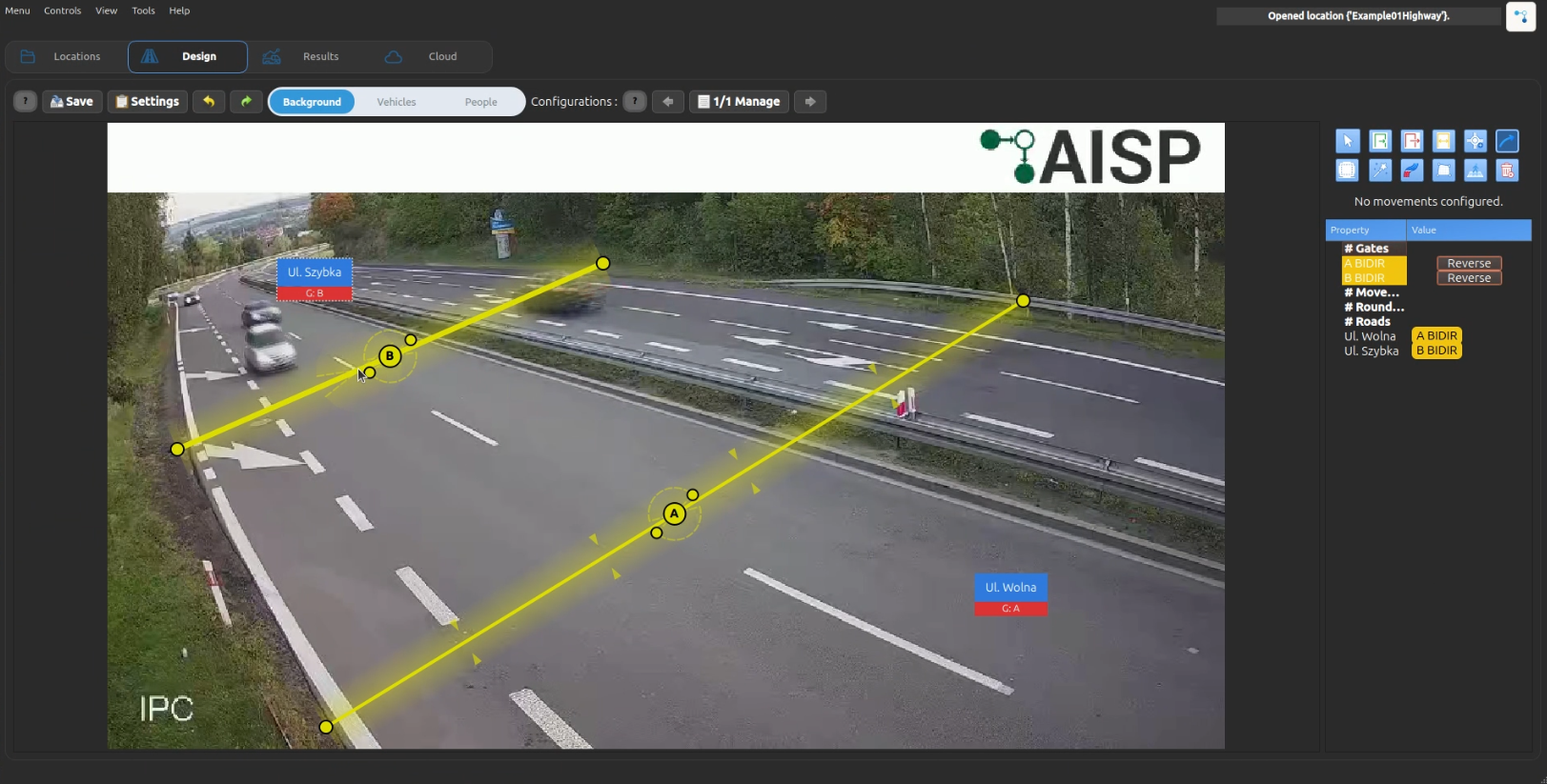
- Select target gate on image (exit point)
- Click the exact position on the target gate line where movement should end
- The movement ID is automatically generated (e.g., "AB" for gate A → gate B)
- The movement receives an automatic color from the palette
- If no valid gates exist, movement creation is not possible
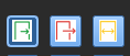
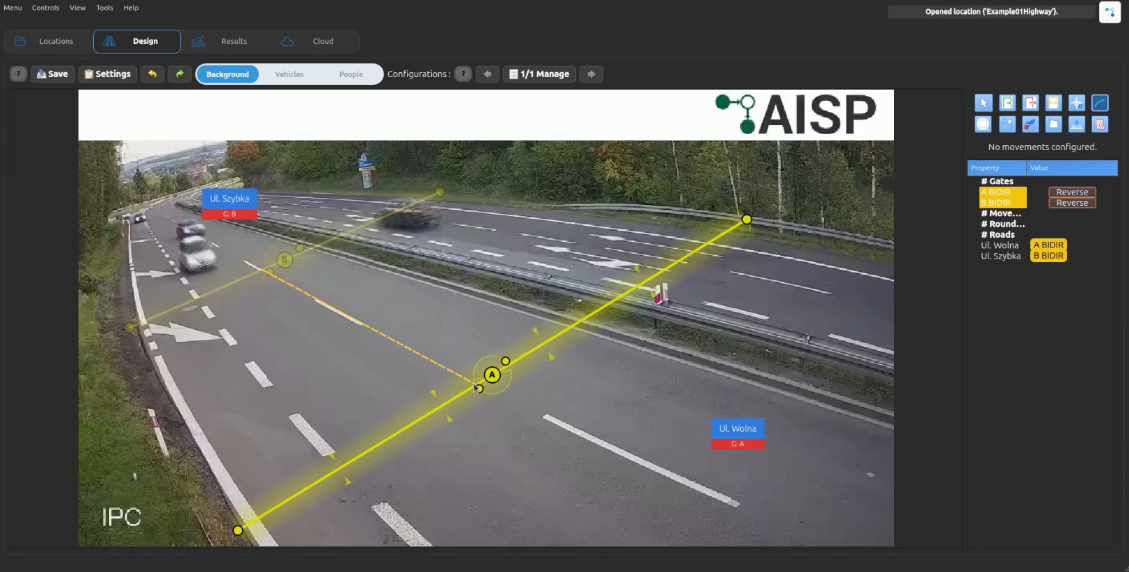
Movement Drawing Preview
- During movement creation, after selecting the source gate, a straight preview line follows the mouse cursor.
- During movement creation, after selecting the source gate, the preview line bends into a straing line while you move the mouse.
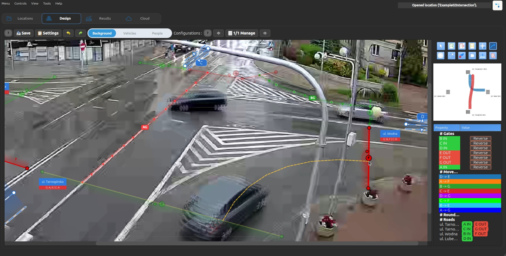
- Movement anchors are stored as normalized position along each gate polyline, so after gate reshaping or moving, movement endpoints stay attached proportionally to the same place on the gate.
- After selecting the target gate, the final movement trajectory is automatically sampled into dense points, so processing and exports still use the standard point-list trajectory format.
Step 3: Run Re-Classification
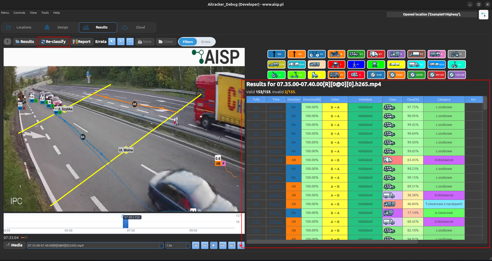 1. Process your video files
2. Vehicles will be automatically assigned to movements based on which gates they cross
3. View results grouped by movements in the reports
1. Process your video files
2. Vehicles will be automatically assigned to movements based on which gates they cross
3. View results grouped by movements in the reports
Vehicle Assignment
Vehicles are assigned to movements based on gate crossing detection:
- Gate crossing detection: System tracks which gates each vehicle crosses
- Gate pair matching: The system identifies the sequence of gates (e.g., A → B)
- Movement assignment: Vehicle is assigned to the corresponding movement (e.g., "AB")
- Guaranteed assignment: Only vehicles that cross defined gate pairs are counted
In the Results tracker table, the Gates column shows only the gates that were actually crossed, in crossing order (for example A → B). Hover over the cell to see the full list with crossing angles, such as A: 30.0° and B: 45.0°.
Best Practices
- Gate placement:
- Place gates at clear entry/exit boundaries
-
Ensure gates are perpendicular to traffic flow
-
Movement definition:
- Define all possible routes through the area
-
Use descriptive gate placement for easier identification
-
Validation:
- Review sample videos to ensure gates are correctly positioned
- Check that movements cover all expected traffic patterns
- Verify vehicle counting accuracy before full processing
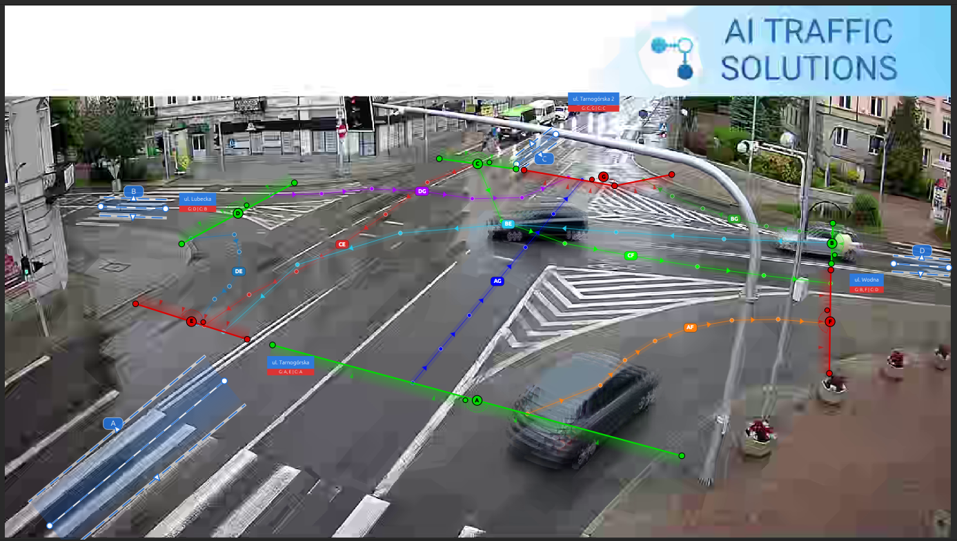
Example: Intersection with 4 Entries
Color Palette
Movements are automatically assigned colors from the system palette in sequence:
- First movement: Blue (#1F77B4)
- Second movement: Orange (#FF7F0E)
- Third movement: Green (#2CA02C)
- Fourth movement: Red (#D62728)
- ... and 17 more colors in rotation
Each classification type (Gates, Movements, Relations) has its own independent color cycler, ensuring consistent visual distinction.
Tips
- Start simple: Begin with basic entry/exit gates before adding complex movements
- Test first: Process a short sample video to verify gate placement
- Review carefully: Check the movements table to ensure all routes are covered